|
| |
TM 9-2320-364-20-5
21-48
21-13. INTERFACE MOUNTING BRACKET REPLACEMENT. (CONT).
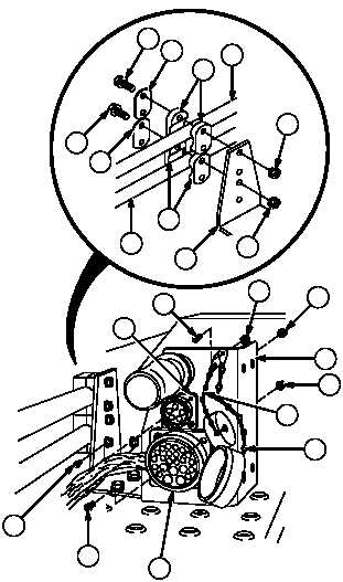
(9)
Install four clamp halves (15), two cover
plates (14), four screws (13), locknuts (12),
tube 2810 (16) and tube 2724 (17) on
interface mounting bracket (7).
(10)
Position MC138 connector (4) through slots
in interface mounting bracket (7) and install
with four screws (11) and locknuts (10).
(11)
Install MC130 connector (2) to interface
mounting bracket (7) with four screws (9)
and locknuts (8).
(12)
Install cap with chain (1) and cap with chain
(3) with screw (6) and locknut (5) on
interface mounting bracket (7).
(13)
Install cap (1) on MC130 connector (2).
(14)
Install cap (3) on MC138 connector (4).
c.
Follow-On Maintenance:
Install quick disconnect, (Para 21-12).
Start engine and check for air leaks.
Remove wheel chocks, (TM 9-2320-364-10).
END OF TASK
10
8
3
1
9
4
2
7
16
13
12
13
15
17
12
6
7
14
14
5
15
11
|