|
| |
TM 9-2320-364-20-5
21-72
21-16. INTERFACE POWERBOX WIRING REPLACEMENT (CONT).
NOTE
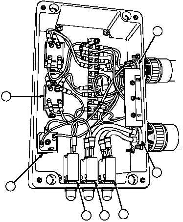
Disconnect only wires required to complete task. Refer to the electrical schematic drawing
3123995 and Table 21-1 Powerbox Wiring for specific powerbox wiring replacement.
Tag and mark wires prior to removal.
(2)
Follow Table 21-1 to disconnect wires.
Table 21-1. Powerbox Wiring
Cable No.
Color
From
To
1785
BLK
4 Pin Connector-A (MC136) (4)
CB27/25AMP - Front (5)
1785
BLK
4 Pin Connector-B (MC136) (4)
CB27/25AMP - Back (5)
1784
BLK
4 Pin Connector-D (MC136) (4)
CB28/25AMP - Front (6)
1784
BLK
4 Pin Connector-C (MC136) (4)
CB28/25AMP - Back (6)
1784
BLK
CB28/25AMP - Front (6)
CB29/2AMP - Front (7)
1789
BLK
CB29/2AMP - Back (7)
Relay R36 / Terminal 30 (8)
1435
BLK
Rectifier/AC (9)
Relay R36 / Terminal 85 (8)
1435A
BLK
Rectifier/+ (9)
MC 135 / 8 Pin Connector - H (10)
AC
4
5
6
7
8
10
AC
86
85
87
30
30
87
85
86
9
|