|
| |
TM 9-2320-364-34-2
12-7
(9)
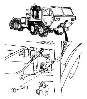
Remove pressure relief valve 12B cover (5).
NOTE
Turning pressure relief valve set
screw to the right will increase
pump output pressure and
turning to the left will decrease
pump output pressure. Each full
turn will change the output
pressure about 400 psi (2,758
kPa).
(10)
Loosen nut (6) and adjust pressure relief
valve with set screw (7).
(11)
Start engine.
(12)
Verify pressure and make necessary
adjustments. Refer to Steps (5)
through (11).
(13)
Tighten nut (6).
(14)
Shut OFF engine.
(15)
Install relief valve 12B cover (5).
(16)
Fully open load valve on flow meter .
(17)
Start engine.
Do not allow load valve to
remain closed for more than 10
seconds. Damage to equipment
could occur.
(18)
While assistant slowly turns steering wheel
in one direction, slowly close load valve.
When load valve is fully closed, pressure
should be 1,800 to 1,825 psi (12,411 to
12,583 kPa) and flow will drop to zero and
front axles will not steer.
(a)
If 1,800 to 1,825 psi (12,411 to 12,583 kPa) are not present, go to Step (19).
(b)
If 1,800 to 1,825 psi (12,411 to 12,583 kPa) are present, sequence valve is adjusted correctly. Shut
OFF engine and go to Step (27).
(19) Shut OFF engine.
|