|
| |
TM 9-2320-364-34-3
16-126
16-18. SWING DRIVE GEAR REDUCER REPLACEMENT (CONT).
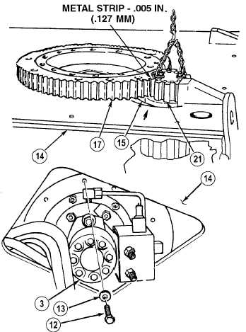
NOTE
The .005 in. (.127 mm) metal
strip must be positioned around
tooth on spur gear and between
spur gear and bearing gear to
obtain .010 in. (.254 mm)
backlash.
(12)
Position .005 in. (.127 mm) metal strip
around tooth of spur gear (21) and position
spur gear (21) with metal strip on bearing
gear (17).
Unsafe welding practices can
cause serious injury from fire,
explosions, or harmful agents.
Allow only authorized personnel
to weld or cut metals, and follow
safety precautions in TC 9-237.
Protective clothing and goggles
must be worn; adequate
protective equipment used, a
suitable fire extinguisher kept
nearby; and requirements of
TC 9-237 strictly followed.
(13)
Tack weld spacer ring (15) to subframe
assembly (14) in accordance to TC 9-237.
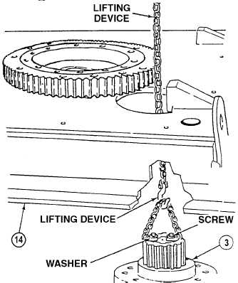
Swing drive gear reducer weighs
140 lbs. (64 kg). Attach suitable
lifting device prior to removal to
prevent possible injury to
personnel.
(14)
With the aid of an assistant and using lifting
device, remove nine screws (12), washers
(13) and swing drive gear reducer (3) from
subframe assembly (14).
(15)
Remove two screws, washers and chain
from swing drive assembly gear reducer
(3).
|