 |
|||
|
|
|||
|
Page Title:
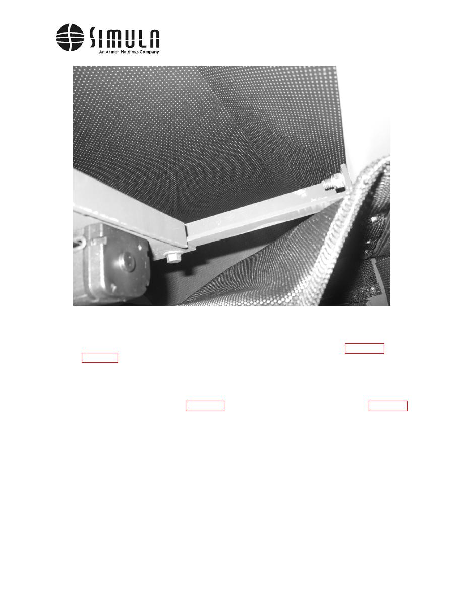
Figure 33. Four-point restraint system (lower portion, behind the seat). |
|
||
| ||||||||||
|
|
 II113300-1-103
Rev. A
hh) The three-point restraint system does not have the "T" bracket shown in Figure 32 and
bottom of the door. There is also a bracket, which the restraint webbing passes through,
that is attached to the inside upper corner of the cab.
ii) Once the type of restraint system is identified, install the Rear Panel Assembly and the
for the four-point restraint system. Position the forward edge of Aft Panel Assembly as
close to the door as possible without interfering with the door's opening and closing.
Several attempts may be required to position the Panel properly.
NOTE
For the three-point restraint system, the bolt that attaches the upper
restraint fitting to the cab should not be over-tightened. When properly
installed, the fitting should rotate freely about the bolt, but not translate
along its length more than 0.020-in.
0037 00-61
|
|
Privacy Statement - Press Release - Copyright Information. - Contact Us |
