|
| |
TM 9-2320-364-20-2
2-911
Remove all jewelry such as rings, dog tags, bracelets, etc. If jewelry contacts positive electrical circuits,
a direct short may result in instant heating of tools, damage to equipment, and injury or death to personnel.
Circuit breakers CB5, CB6, CB12, CB20, CB22, CB23 and relays R3, R13 - R19, R26, R28, R32, R33 are
always electrically hot and can cause severe injury to personnel. Non-metallic tools shall be used
when removing relays.
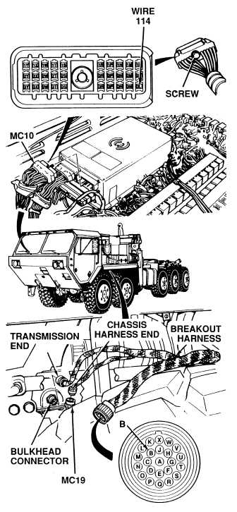
(1) Remove 15 screws and two
ECB covers.
(2) Loosen screw and disconnect
connector MC10 from ATEC ECU.
(3) Connect transmission connector
MC19 to breakout harness
chassis end connector.
(4) Is there continuity between connector
MC10 and breakout harness
connector on the solenoid harness
input and output wires listed in
(Table 2-31)?
(a) If there is no continuity, repair
wire(s) (Table 2-31)
(see schematic Fig 2-22) or notify
DS Maintenance.
(b) If there is continuity,
cab/transmission harness wires
are OK.
(5) Disconnect breakout harness
transmission and chassis end
connectors from transmission
bulkhead and MC19 connector.
(6) Connect transmission connector
MC19 to transmission bulkhead
connector.
(7) Install connector MC10 to ATEC ECU
and tighten screw.
(8) Install two ECB covers and 15 screws.
(9) Install left rear skirt on underside of
fender (Para 17-34).
CONTINUITY TEST
NOTE
Table 2-31 lists ECU and transmission bulkhead connectors
MC10 and MC19 and the solenoid wires and connector terminals
used as test points for the following procedures.
Table 2-31. ECU and Transmission Bulkhead
Connectors.
ATEC WIRE HARNESS
SOLENOID WIRES TEST POINTS
Solenoid
Conn.
(Code No.)
J(41)
F(42)
D(43)
C(44)
B(45)
A(46)
G(51)
E(52)
H(53)
ECU Conn. MC10
Term. (Wire No.)
Bulkhead
Term. (Wire No.)
3L(114)
3M(111)
2T(120)
1W(105)
2T(120)
1S(110)
3L(114)
1S(110)
1T(115)
1W(105)
1T(115)
3T(121)
1Y(107)
2Y(109)
2W(119)
3Y(117)
2M(108)
B(114)
D(111)
V(120)
U(105)
V(120)
W(110)
B(114)
W(110)
T(115)
U(105)
T(115)
C(121)
O(107)
L(109)
M(119)
N(117)
K(108)
|