|
| |
TM 9-2320-364-20-2
2-1221
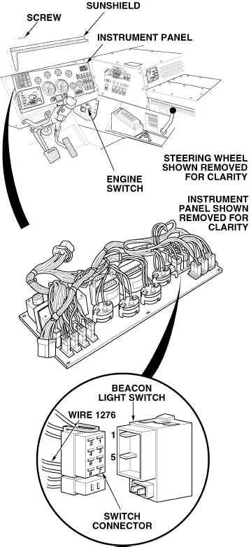
(1) Remove ten screws and sunshield
from instrument panel.
(2) Pull top of instrument panel towards
steering wheel.
(3) Remove beacon light switch.
(4) Set multimeter select switch to
volts dc.
(5) Connect positive (+) multimeter lead
to wire 1276 at beacon light switch
connector, terminal 5.
(6) Connect negative (–) multimeter
lead to a known good ground.
(7) Turn ON ENGINE switch
(TM 9-2320-364-10).
(a) If 10 to 14 vdc are not present,
turn OFF ENGINE switch
and repair wire 1276 (see
schematic Fig 2-28).
(b) If 10 to 14 vdc are present,
wire 1276 is OK.
(8) Turn OFF ENGINE switch.
VOLTAGE TEST
Remove all jewelry such as rings, dog tags, bracelets, etc. If jewelry or tools contact positive electrical
circuits, a direct short may result. Damage to equipment, injury or death to personnel may occur.
(1) Turn on beacon light switch
(TM 9-2320-364-10).
(2) Set multimeter select switch to ohms.
(3) Is there continuity between terminals
1 and 5 on beacon light switch?
(a) If there is no continuity, replace
beacon light switch (Para 7-27).
(b) If there is continuity, beacon light
switch is OK.
(4) Install beacon light switch.
(5) Install instrument panel and
sunshield with ten screws.
CONTINUITY TEST
|