|
| |
TM 9-2320-364-20-2
2-1271
(1) Set multimeter select switch to
volts dc.
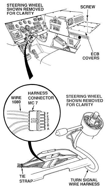
(2) Connect positive (+) multimeter lead
to connector MC7, terminal F.
(3) Connect negative (–) multimeter lead
to a known good ground.
(4) Push in hazard warning button
(TM 9-2320-364-10).
(a) If 2 to 10 vdc are not present,
perform Steps (5) through (7)
below and replace flasher M5
(Para 7-97).
(b) If 2 to 10 vdc are present,
replace turn signal switch/dimmer
switch (Para 7-35) and perform
Steps (5) through (8) below.
(5) Pull out hazard warning button.
(6) Connect connector MC7 to turn signal
switch/dimmer switch connector.
(7) Install cable ties as necessary.
(8) Install two ECB covers and 15 screws.
VOLTAGE TEST
Circuit breakers CB5, CB6, CB12, CB20, CB22, CB23 and relays R3, R13 - R19, R26, R28, R32, R33
are always electrically hot and can cause severe injury to personnel. Care must be exercised when
working under the electrical circuit board cover.
Remove all jewelry such as rings, dog tags, bracelets, etc. If jewelry or tools contact positive electrical
circuits, a direct short may result. Damage to equipment, injury or death to personnel may occur.
(1) Turn ON ENGINE switch
(TM 9-2320-364-10).
(2) Turn on turn signals.
(3) Observe turn signals.
(a) If turn signals do not operate, fault
not corrected. Perform Steps (4)
and (5) below and notify DS
Maintenance.
(b) If turn signals operate, fault has
been corrected.
(4) Turn off turn signals.
(5) Turn OFF ENGINE switch.
VERIFY REPAIR
NOTE
Voltage measured in Step (3) below will
pulsate 2 to 10 vdc.
|