|
| |
TM 9-2320-364-20-2
2-1627
DUVAC
COVER
WASHER
LOCK–
WASHER
SCREW
DOOR
SHOWN
REMOVED
FOR CLARITY
PANEL
WASHER
LOCKWASHER
SCREW
FIRE
EXTINGUISHER
BRACKET
LOCKWASHER
WASHER
SCREW
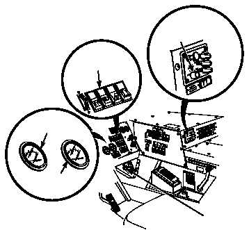
ENGINE
SWITCH
HEADLIGHT
SWITCH
12 vdc
VOLTMETER
24 vdc
VOLTMETER
FAN
CONTROL
SWITCH
(1) Start engine and turn on headlights
and heater (TM 9-2320-364-10).
(a) If 13-14 vdc are not indicated on
12 vdc voltmeter and 26-28 vdc
are not indicated on 24 vdc
voltmeter, fault not corrected.
Perform Steps (2) through (6)
below and notify Supervisor.
(b) If 13-14 vdc are indicated on 12
vdc voltmeter and 26-28 vdc are
indicated on 24 vdc voltmeter,
fault has been corrected.
(2) Turn off heater, headlights and engine
switch.
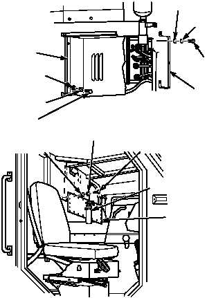
(3) Install bracket with two screws,
lockwashers and washers.
(4) Install DUVAC cover with four screws,
lockwashers and washers.
(5) Install cab engine access panel with
22 screws, lockwashers and washers.
(6) Install fire extinguisher.
VERIFY REPAIR
Terminal 1 and terminal 2 at DUVAC controller are electrically hot all of the time. Ensure DUVAC cover or
bracket does not contact either terminal. Damage to equipment, injury or death to personnel may occur.
NOTE
DUVAC controller should reset to the 24 vdc
charge mode approximately every 55 to 60
seconds. Observe 24 vdc voltmeter for at
least two minutes to allow the regulator timer
to cycle.
|