|
| |
TM 9-2320-364-20-3
2-2015
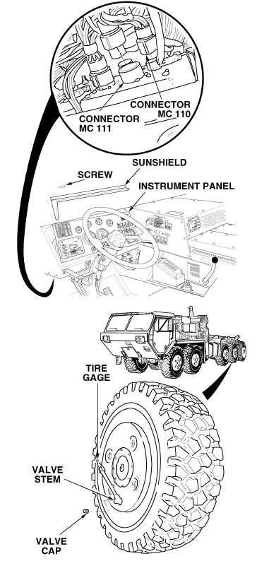
(1) Remove ten screws and sunshield
from instrument panel.
(2) Pull top of instrument panel
toward steering wheel.
(3) Disconnect front manifold harness
connector MC110 from back of
CTIS controller.
(4) Disconnect rear manifold harness
connector MC111 from back of
CTIS controller.
(5) Connect harness connector MC111
into CTIS controller where
connector MC110 was
disconnected.
(6) Connect harness connector MC110
into CTIS controller where
connector MC111 was
disconnected.
(7) Remove valve cap from any wheel
valve stem on Axles No. 3 through
No. 5.
(8) Using tire gage, deflate any one tire
on Axles No. 3 through No. 5 to 40
psi (276 kPa).
(9) Start engine (TM 9-2320-364-10).
(10) As assistant pushes CTIS START
button, observe deflated tires.
(a)
If deflated tires do not inflate
to correct pressures,
turn OFF ENGINE switch and
replace CTIS controller
(Para 13-7).
(b)
If deflated tires inflate to
correct pressures, CTIS
controller is OK.
(11) Position LHS in transit position.
(12) Turn OFF ENGINE switch.
(13) Disconnect and connect
connectors MC 110 and MC111 to
correct CTIS controller connectors.
CTIS CONTROLLER TEST
Remove all jewelry such as rings, dog tags,
bracelets, etc. If jewelry or tools contact
positve electrical circuits, a direct short
may result. Damage to equipment, injury or
death to personnel may occur.
NOTE
When switching MC110 connector and MC111
connector, tire pressures of front axles and
rear axles will also be reversed.
|

