|
| |
TM 9-2320-364-20-3
2-2149
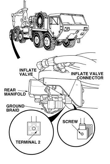
(1) Loosen screw and disconnect inflate
valve connector.
(2) Set multimeter select switch to volts dc.
(3) Connect positive (+) multimeter lead to
inflate valve harness connector,
terminal 2.
(4) Connect negative (–) multimeter lead to
rear manifold ground braid.
(5) Turn ON ENGINE switch
(TM 9-2320-364-10).
(6) Assistant pushes CTIS START button.
(a) If 10 to 14 vdc (pulsating) are not
present, turn OFF ENGINE switch
and replace rear manifold
(Para 13-9).
(b) If 10 to 14 vdc (pulsating) are
present, turn OFF ENGINE switch
and go to Step 25 of this Fault.
VOLTAGE TEST
Remove all jewelry such as rings, dog tags, bracelets, etc. If jewelry or tools contact positive electrical
circuits, a direct short may result. Damage to equipment, injury or death to personnel may occur.
10 to 14 vdc (pulsating) will cycle at least five
times, then drop to 0 vdc.
During the cycle course of this test, 10 to 14
vdc will be measured intermittently, then
drop to 0 vdc.
Voltmeter must read 10 to 14 vdc at least
one time before dropping to 0 vdc.
NOTE
|