|
| |
TM 9-2320-364-20-3
2-2275
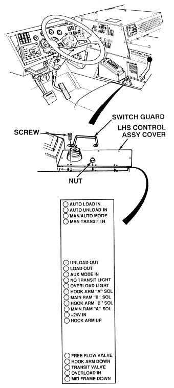
(1) Remove eight nuts, screws and
switch guard from LHS control
assy.
(2) Carefully lift off LHS control assy
cover. Do not allow cover to dangle
by joystick connecting wires.
(3) Observe red indicator light at bottom
of LHS control assy while turning ON
ENGINE switch (TM 9-2320-364-10).
(a) If NO TRANSIT LIGHT lamp is
illuminated, turn OFF ENGINE
switch and replace LHS control
assy (Para 7-40).
(b) If NO TRANSIT LIGHT lamp is not
illuminated, perform Steps (4)
through (7) below.
(4) Raise LHS completely.
(5) Observe red indicator light at bottom
of LHS control assy while turning
ON ENGINE switch.
(a) If NO TRANSIT LIGHT lamp is not
illuminated, turn OFF ENGINE
switch and replace LHS control
assy (Para 7-40).
(b) If NO TRANSIT LIGHT lamp is
illuminated, LHS control assy
is OK.
(6) Turn OFF ENGINE switch.
(7) Install cover, switch guard and eight
nuts on LHS control assy.
Keep clear of equipment when equipment is being raised or lowered. Equipment may fall and cause
serious injury or death to personnel.
Remove all jewelry such as rings, dog tags, bracelets, etc. If jewelry or tools contact positive electrical
circuits, a direct short may result. Damage to equipment, injury or death to personnel may occur.
VISUAL INSPECTION
|