|
| |
TM 9-2320-364-20-3
2-2469
(1) Put LHS in transit position
(TM 9-2320-364-10).
(2) Set multimeter selector switch to
volts dc.
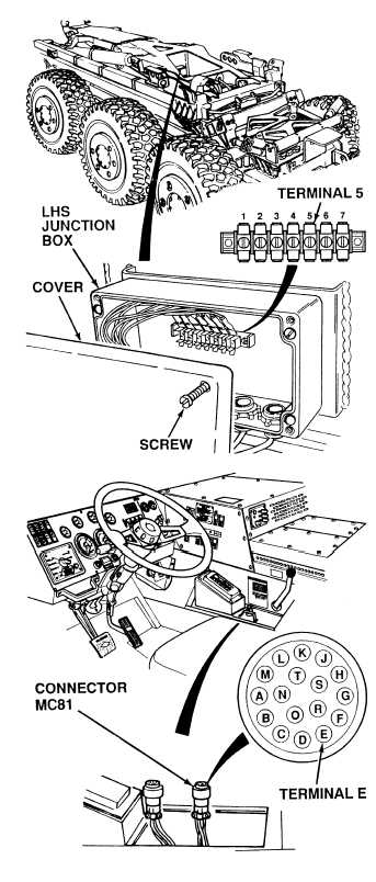
(3) Connect positive (+) multimeter
lead to LHS junction box, terminal 5.
(4) Connect negative (–) multimeter
lead to a known good ground.
(5) Turn ON ENGINE switch.
(a) If there are 22 to 28 vdc
present, perform Step (10)
below and replace proximity
switch (hook arm up)
(Para 7-38).
(b) If there are not 22 to 28 vdc
present, perform Step (6)
below.
(6) Start engine.
(7) Raise hook arm completely.
(8) Turn OFF ENGINE switch.
(9) Turn ON ENGINE switch.
(a) If there are not 22 to 28 vdc
present, perform Step (10)
below and replace proximity
switch (hook arm up)
(Para 7-38).
(b) If there are 22 to 28 vdc
present, proximity switch is
OK.
(10) Start engine.
(11) Put LHS in transit position.
(12) Turn OFF ENGINE switch.
VOLTAGE TEST
Remove all jewelry such as rings, dog tags, bracelets, etc. If jewelry or tools contact positive electrical
circuits, a direct short may result. Damage to
(1) Connect LHS junction box terminal 5
to a known good ground using
jumperwire.
(2) Remove control assembly
(Para 7-40).
(3) Set multimeter selector switch to
ohms.
(4) Is there continuity between harness
connector MC81, terminal E and a
known good ground?
(a) If there is no continuity, repair wire
1466 (see schematic Fig 2-52) or
notify DS Maintenance.
(b) If there is continuity, wire
1466 is OK.
(5) Remove jumperwire from LHS
junction box terminal 5 and ground.
(6) Close LHS junction box and tighten
four screws.
CONTINUITY TEST
|