|
| |
TM 9-2320-364-20-4
7-365
Materials/Parts
Adhesive (Item 8, Appendix C)
(Model A connector only)
Cable Ties (Item 25, Appendix C)
Compound, Corrosion Preventive
(Item 35, Appendix C)
This task covers:
a. Removal
b. Installation
c. Follow-On Maintenance
INITIAL SETUP
Tools and Special Tools
Tool Kit, Electric (Item 73, Appendix G)
Tool Kit, General Mechanic’s: Automotive
(Item 74, Appendix G)
Weatherpak Crimper (Item 76, Appendix G)
7-103. 7-PIN ELECTRICAL CONNECTOR REPLACEMENT.
Materials/Parts- Continued
Tags, Identification (Item 88, Appendix C)
Locknut (4) (Item 133, Appendix F)
Equipment Condition
Engine OFF, (TM 9-2320-364-10)
Wheels chocked, (TM 9-2320-364-10)
Batteries disconnected, (Para 7-87)
a.
Removal.
6
3
5
2
4
1
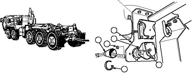
NOTE
Front connector MC27 and rear connector MC16 are removed the same way. Rear
connector MC16 is shown.
There are two types of 7-pin electrical connectors. Model B replaced Model A.
Model A has a rubber boot covering the back.
Model B uses rubber push on connectors on the back.
Perform steps (1) through (4) for Model A connectors.
Tag and mark wires prior to removal.
Loosen cushion clips as required.
(1)
Remove cable tie (1) and rubber boot (2) from connector MC16 (3).
(2)
Remove two locknuts (4), screws (5) and connector MC16 (3) from mounting bracket (6). Discard
locknuts.
|