|
| |
TM 9-2320-364-20-4
7-367
b.
Installation.
NOTE
Perform Steps (1) through (11)
for model B connector.
Perform Steps (4) through (11)
if replacing model A connector
with model B connector.
Perform Steps (1) through (8)
if terminal or seal boot is
damaged on model B
connector.
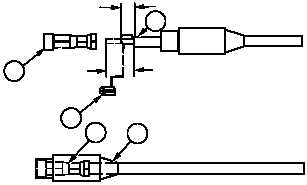
Tapered end of seal boot is
installed on wire first.
(1)
Slide seal boot (15) over wire (16) to expose
terminal (17).
(2)
Cut off terminal (17) at end of wire (16).
Discard terminal.
NOTE
Perform steps (3) and (4) if
seal boot is damaged.
(3)
Remove and discard seal boot (15).
(4)
Install seal boot (15) on wire (16).
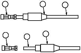
(5)
Remove 7/16 in. (11.11 mm) of insulation
(18) from end of wire (16).
(6)
Fold over exposed end of wire (16) to 7/32
in. (5.56 mm).
NOTE
Replacement kit comes with large
and small terminals. Small
terminals must be used.
(7)
Install terminal (17) on wire (16).
(8)
Slide seal boot (15) over terminal (17).
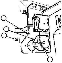
(9)
Install MC16 connector (5) on mounting bracket
(6) with two screws (7) and locknuts (8).
SERVICE
6
3
5
4
17
17
16
16
7/32 IN.
(5.56 MM)
7/16 IN.
(11.11 MM)
18
17
17
16
15
15
16
|