|
| |
TM 9-2320-364-20-4
12-57
Materials/Parts
Cable Ties (Item 14, Appendix C)
Sealing Compound (Item 72, Appendix C)
Tags, Identification (Item 88, Appendix C)
This task covers:
a. Removal
b. Installation
c. Follow-On Maintenance
INITIAL SETUP
Equipment Condition
Engine OFF, (TM 9-2320-364-10)
Wheels chocked, (TM 9-2320-364-10)
Air system drained, (TM 9-2320-364-10)
LHS fully extended, (TM 9-2320-364-10)
Tools and Special Tools
Tool Kit, General Mechanic’s: Automotive
(Item 74, Appendix G)
Wrench, Combination 1-1/16 in.
(Item 78, Appendix G)
12-14. SERVICE RELAY VALVE NO. 2 REPLACEMENT.
Materials/Parts - Continued
Locknut (2) (Item 133, Appendix F)
Lockwasher (2) (Item 180, Appendix F)
NOTE
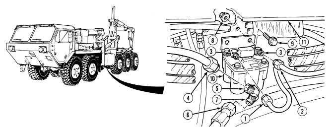
Mark and tag air lines prior to removal.
Remove cable ties as required.
(1)
Remove air line 2668 (1) and air line 2639 (2) from elbows (3).
(2)
Remove air line 2011 (4) from elbow (5).
(3)
Remove air line 2545 (6) from elbow (7).
(4)
Remove two locknuts (8), screws (9) and service relay valve (10) from frame (11). Discard locknuts.
|