|
| |
TM 9-2320-364-20-5
15-37
Materials/Parts
Adhesive (Item 8, Appendix C),
(Model A connector only)
Cable Ties (Item 25, Appendix C)
Locknut (5) (Item 91, Appendix F)
Locknut (2) (Item 107, Appendix F)
This task covers:
a. Removal
b. Installation
c. Follow-On Maintenance
INITIAL SETUP
Personnel Required
Two
Equipment Condition
Engine OFF, (TM 9-2320-364-10)
Wheels chocked, (TM 9-2320-364-10)
Gladhand removed, (Para 12-43)
Tools and Special Tools
Tool Kit, General Mechanic’s: Automotive
(Item 74, Appendix G)
15-14. SERVICE GLADHAND BRACKET REPLACEMENT.
Materials/Parts - Continued
Locknut (2) (Item 140, Appendix F)
a.
Removal.
NOTE
There are two types of 7-pin electrical connectors. Model B replaced Model A.
Model A has a rubber boot covering the back.
Model B uses rubber push on connectors on the back.
Perform Step (1) for Model A connector.
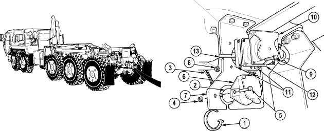
(1)
Remove cable tie (1) and slide boot (2) back on chassis wire harness (3).
(2)
Remove two locknuts (4) and screws (5) from MC16 connector (6) and bracket (7). Discard locknuts.
(3)
Pull MC16 connector (6) toward rear of truck and guide chassis wire harness (3) down through slot on
bracket (7).
(4)
Remove four locknuts (8), screws (9), connector cover (10) and two spacers (11) from MC15 connector
(12) and bracket (7). Discard locknuts.
(5)
Pull MC15 connector (12) toward rear of truck and guide wires (13) through slot on side of bracket (7).
|