|
| |
TM 9-2320-364-20-5
15-40
Materials/Parts
Lockwasher (2) (Item 180, Appendix F)
Lockwasher (Item 211, Appendix F)
This task covers:
a. Removal
b. Installation
c. Follow-On Maintenance
INITIAL SETUP
Equipment Condition
Engine OFF, (TM 9-2320-364-10)
Wheels chocked, (TM 9-2320-364-10)
Angled rollers removed, (Para 15-16)
Rear roller assembly removed, (Para 15-17)
Tools and Special Tools
Tool Kit, General Mechanic’s: Automotive
(Item 74, Appendix G)
Lifting Device, Minimum Capacity 375 lbs
(170 kg)
15-15. HORIZONTAL ROLLER REPLACEMENT.
a.
Removal.
Rear roller assembly weighs 375
lbs (170 kg). Attach suitable
lifting device prior to removal to
prevent possible injury to
personnel.
NOTE
Both right and left hand
horizontal rollers are removed
the same way. Right horizontal
roller is shown.
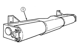
(1)
Using lifting device, place rear roller
assembly (1) on clean work surface.
|