|
| |
TM 9-2320-364-20-5
16-4
Materials/Parts
Locknut (2) (Item 92, Appendix F)
Locknut (2) (Item 93 Appendix F)
This task covers:
a. Axle No. 1 Shock Absorber Mount Replacement
e. Axle No. 4 Shock Absorber Mount Replacement
b. Axle No. 2 Shock Absorber Mount Replacement
f. Follow-On Maintenance
c. Axle No. 3 Shock Absorber Mount Replacement
INITIAL SETUP
Personnel Required
Two
Equipment Condition
Engine OFF, (TM 9-2320-364-10)
Wheels chocked, (TM 9-2320-364-10)
Shock absorber removed, (Para 16-2)
Front access cover opened (Axle No. 1 only),
(TM 9-2320-364-10)
Tools and Special Tools
Tool Kit, General Mechanic’s: Automotive
(Item 74, Appendix G)
Socket, Wrench Set 3/4 in. (Item 61, Appendix G)
Wrench, Combination 1-1/8 in.
(Item 79, Appendix G)
Wrench, Torque (0 to 300 lb-ft [0 to 407 N.m])
(Item 96, Appendix G)
16-3. SHOCK ABSORBER MOUNTS REPLACEMENT.
NOTE
Right and left side mounts are
removed the same way.
a.
Axle No. 1 Shock Absorber Mount
Replacement.
(1)
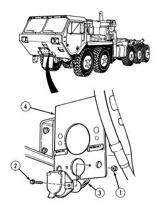
Removal.
(a)
Remove two locknuts (1), screws (2)
and wire harness (3) from
crossmember (4). Discard locknuts.
|