|
| |
TM 9-2320-364-20-5
17-45
Materials/Parts
Locknut (7) (Item 93, Appendix F)
This task covers:
a. Removal
b. Installation
c. Follow-On Maintenance
INITIAL SETUP
Equipment Condition
Engine OFF, (TM 9-2320-364-10)
Wheels chocked, (TM 9-2320-364-10)
Main hydraulic reservoir removed, (Para 20-12)
Tools and Special Tools
Tool Kit, General Mechanic’s: Automotive
(Item 74, Appendix G)
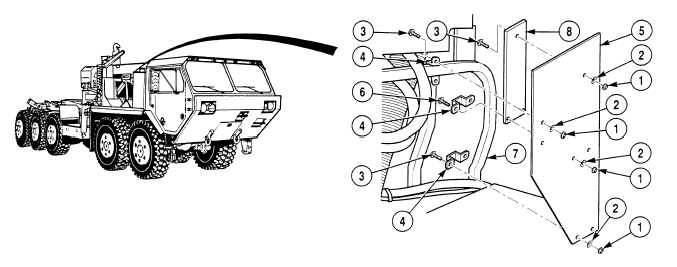
17-18. RIGHT HAND BAFFLE REPLACEMENT.
(1)
Remove four locknuts (1) washers (2), screws (3) and two brackets (4) from right hand baffle (5).
(2)
Remove two locknuts (1), screws (6), bracket (4) and right hand baffle (5) from right side power module
frame (7).
(3)
Remove locknut (1), washer (2), plate (8) and screw (3) from right hand baffle (5).
b.
Installation.
(1)
Position plate (8) on right hand baffle (5) with screw (3), washer (2) and locknut (1).
(2)
Position right hand baffle (5) on right side power module frame (7) with bracket (4), two screws (6),
washers (2) and locknuts (1).
(3)
Position two brackets (4) on right side power module frame (7) and right hand baffle (5) with four
screws (3), washers (2) and locknuts (1).
(4)
Tighten seven locknuts (1).
c.
Follow-on Maintenance:
Install main hydraulic reservoir, (Para 20-12).
Remove wheel chocks, (TM 9-2320-364-10).
END OF TASK
|