|
| |
TM 9-2320-364-20-5
20-21
(16)
Install two wires (15) through nut (26),
washer (27), gasket (28), cord grip (23) and
fan control solenoid valve (2).
(17)
Position heatshrink (29) on wire (15).
(18)
Position ends of wire (15) and fan control
solenoid valve wire (30) in conductor splice
(31) and crimp in place.
(19)
Install heatshrink (29) on conductor splice
(31).
(20)
Repeat Steps (17) through (19) for
remaining wire.
(21)
Install gasket (28), washer (27) and
nut (26) on cord grip (23).
(22)
Install cover (21) and gasket (22) on
fan control solenoid valve (2) using
four screws (20).
NOTE
Fan control solenoid valve may or
may not have spacers in Step
(23).
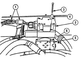
(23)
Install fan control solenoid valve (2) on
subplate (5) using four spacers (4) and
screws (3). Tighten to 32 lb-in (3 N.m).
(24)
Apply hydraulic oil to four preformed
packings (6) and install on subplate (5).
(25)
Connect MC76 connector (1).
f.
Follow-On Maintenance:
Install Electronic Control Box (ECB), (Para 17-23).
Start engine. Allow engine to run for three minutes, (TM 9-2320-364-10).
Shut OFF engine, (TM 9-2320-364-10).
Check for hydraulic leaks, (TM 9-2320-364-10).
Remove wheel chocks, (TM 9-2320-364-10).
END OF TASK
26
27
28
23
2
15
29
31
30
21
22
20
|