|
| |
TM 9-2320-364-20-5
21-64
This task covers:
a. Removal
c. Cleaning/Inspection
e. Installation
b. Disassembly
d. Assembly
f. Follow-On Maintenance
INITIAL SETUP
Materials/Parts
Solvent, Drycleaning (Item 87, Appendix C)
Tags, Identification (Item 88, Appendix C)
Equipment Condition
Engine OFF, (TM 9-2320-364-10)
Wheels chocked, (TM 9-2320-364-10)
Batteries disconnected, (Para 7-87)
Interface wiring harness disconnected,
(Para 21-14)
Powerbox wiring removed, (Para 21-16)
Tools and Special Tools
Tool Kit, General Mechanic’s: Automotive
(Item 74, Appendix G)
Drill, Electric, Portable 1/4”
(Item 17, Appendix G)
Drill Set, Twist (Item 19, Appendix G)
Gloves, Chemical Oil Protective
(Item 28, Appendix G)
Goggles, Industrial (Item 30, Appendix G)
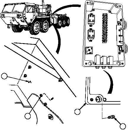
21-15. INTERFACE POWERBOX ASSEMBLY REPAIR.
Materials/Parts (cont)
Locknut (4) (Item 104, Appendix F)
Locknut (4) (Item 106, Appendix F)
Locknut (4) (Item 107, Appendix F)
Lockwasher (3) (Item 205, Appendix F)
a.
Removal.
(1)
Remove four screws (1), locknuts (2) and powerbox (3) from left front fender (4). Discard locknuts.
1
3
2
4
|