|
| |
TM 9-2320-364-20-5
21-65
b.
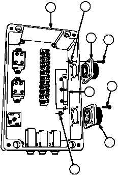
Disassembly.
NOTE
Note location and position of
connectors, terminal strip, relays
and rectifier prior to removal.
(1)
Remove four locknuts (1), screws (2) and 8
pin connector (3) from powerbox (4).
Discard locknuts.
(2)
Remove four locknuts (5), screws (6), 4 pin
connector (7) and LED (8) from powerbox
(4). Discard locknuts.
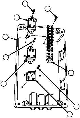
(3)
Remove two screws (9) and terminal strip
(10) from powerbox (4).
(4)
Remove four screws (11) and two relays (12)
from powerbox (4).
(5)
Remove screw (13) and rectifier (14) from
powerbox (4).
4
2
6
3
7
5
1
8
11
12
9
4
11
12
10
13
14
|