|
| |
TM 9-2320-364-20-5
23-5
This task covers:
a. Removal
b. Installation
c. Follow-On Maintenance
INITIAL SETUP
Equipment Condition
Engine OFF, (TM 9-2320-364-10)
Wheels chocked, (TM 9-2320-364-10)
Tools and Special Tools
Tool Kit, General Mechanic’s: Automotive
(Item 74, Appendix G)
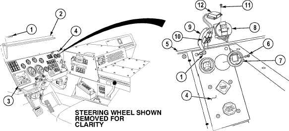
23-3. AIR RESTRICTION INDICATOR REPLACEMENT.
a.
(1)
Remove six screws (1) and sunshield (2) from dash (3) and air dash panel (4).
(2)
Remove two screws (1) from air dash panel (4).
(3)
Pull air dash panel (4) away from dash (5).
(4)
Remove two screws (6) from gage face (7).
(5)
Remove gage face (7) from restriction indicator (8).
Ensure instrument panel is only pulled away from dash far enough to route restrictor indicator between
instrument panel and dash. If instrument panel is pulled away further than necessary, damage to
equipment may result.
(6)
Route restrictor indicator (8) up between air dash panel (4) and dash (5).
(7)
Remove restrictor indicator (8) from hose (9).
(8)
Disconnect MC125 connector (10).
NOTE
Perform Step (9) if replacing light kit.
(9)
Remove two screws (11) and light kit (12) from restrictor indicator (8).
|