|
| |
TM 9-2320-364-20-5
23-6
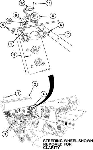
23-3. AIR RESTRICTION INDICATOR REPLACEMENT (CONT).
b.
Installation.
NOTE
Perform Step (1) if light kit was
removed.
(1)
Install light kit (12) on restrictor indicator
(8) using two screws (11).
(2)
Pull air dash panel (4) away from dash (5).
(3)
Connect MC125 connector (10).
(4)
Install restrictor indicator (8) on hose (9).
Ensure air dash panel is only
pulled away from dash far enough
to route restrictor indicator
between air dash panel and dash.
If air dash panel is pulled away
further than necessary, damage
may result to equipment.
(5)
Route restrictor indicator (8) down through
air dash panel (4) and dash (5).
NOTE
Ensure restrictor indicator is
positioned in upright position in
air dash panel.
(6)
Position restrictor indicator (8) in air dash
panel (4).
(7)
Install gage face (7) in air dash panel (4)
with two screws (6).
(8)
Position air dash panel (4) on dash (5).
(9)
Install two screws (1) in air dash panel (4).
(10)
Install sunshield (2) on dash (3) and air
dash panel (4) with six screws (1).
c.
Follow-On Maintenance:
Remove wheel chocks, (TM 9-2320-364-10).
END OF TASK
|