|
| |
TM 9-2320-364-34-2
12-34
Materials/Parts
Key (2) (Item 137, Appendix E)
This task covers:
a. Removal
b. Installation
c. Follow-On Maintenance
INITIAL SETUP
Equipment Condition
Engine OFF, (TM 9-2320-364-10)
Wheels chocked, (TM 9-2320-364-10)
Axle No. 5 steering shaft removed,
(TM 9-2320-364-20)
Tools and Special Tools
Tool Kit, General Mechanic’s
(Item 240, Appendix F)
Pan, Drain 4 gal (Item 144, Appendix F)
Press, Arbor, Hand Operated
(Item 162, Appendix F)
Wrench, Torque (0 to 175 lb-ft [0-237 N.m])
(Item 277, Appendix F)
12-6. 2.21:1 GEAR REDUCER AND INTER-STEERING SHAFT REPLACEMENT.
Materials/Parts - Continued
Locknut (2) (Item 169, Appendix E)
Locknut (3) (Item 201, Appendix E)
Locknut (2) (Item 213, Appendix E)
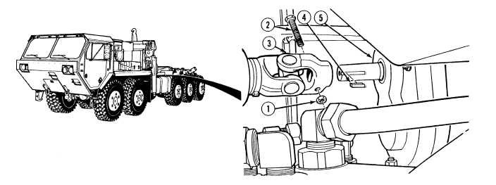
NOTE
Removal of 2.21:1 gear reducer from truck equipped with crane as shown. Removal from truck
without crane is same.
(1)
Remove locknut (1), screw (2), steering shaft (3) and key (4) from gear reducer (5). Discard locknut
and key.
|