|
| |
TM 9-2320-364-34-2
3-72
3-7. CYLINDER HEAD ASSEMBLY REPLACEMENT (CONT).
NOTE
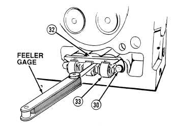
There must be 0.005 in. (0.127
mm), but not more than 0.010 in.
(0.254 mm), clearance between
cam follower guide and cam
follower.
(23)
Insert 0.005 in. (0.127 mm) feeler gage
between cam follower guide (32) and legs of
cam followers (33).
(24)
Tap cam follower guide (32) lightly with soft
faced hammer until feeler gage is snug.
(25)
Tighten screws (30) on cam follower
guide (32) to 180 lb-in (20 N.m).
(26)
Remove feeler gage from cam follower
guide (32) and legs of cam followers (33).
(27)
Re-insert 0.005 in. (0.127 mm) feeler gage
between cam follower guide (32) and legs of
cam followers (33).
(28)
If there is not enough clearance, loosen
screws (30), move guide (32) and repeat
Steps (23) through (26) until proper
clearance is obtained.
(29)
If proper clearance cannot be obtained,
replace cam follower guide (32).
(30)
Repeat Steps (17) through (29) for each cam
follower and push rod being installed.
|