|
| |
TM 9-2320-364-34-2
3-101
(8)
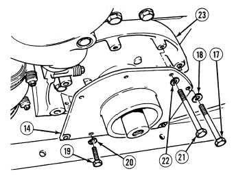
Position trunnion plate (14) against
crankcase cover (23).
(9)
Position four lockwashers (18) and
screws (17) in trunnion plate (14).
(10)
Position two lockwashers (20) and
screws (19) in trunnion plate (14).
(11)
Position two lockwashers (22) and
screws (21) in trunnion plate (14).
(12)
Tighten screws (19) and (21) in trunnion
plate (14).
(13)
Tighten four screws (17) in trunnion
plate (14) to 80 to 90 lb-ft (108 to 122
N.m).
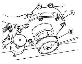
(14)
Coat inside of ring (13) with light coat of
grease.
NOTE
Install ring in position noted
prior to removal.
(15)
Install ring (13) on trunnion plate (14).
(16)
Position two washers (15) on mounts (16).
NOTE
Ensure washers and mounts
remain seated while lowering
trunnion assembly on engine
support.
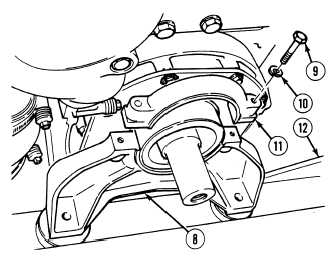
(17)
Position lower trunnion assembly (8) on
engine support (12).
(18)
Install upper trunnion assembly (11) on
lower trunnion assembly (8) with two
lockwashers (10) and screws (9). Tighten
screws to 45 to 50 lb-ft (61 to 68 N.m).
|