|
| |
TM 9-2320-364-34-2
3-164
3-29. ENGINE OIL COOLER ASSEMBLY REPLACEMENT (CONT).
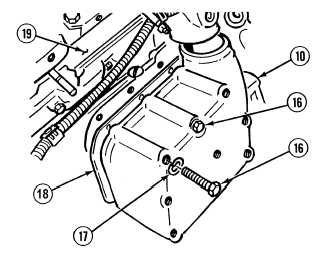
There are 12 screws in oil cooler.
Ensure only 11 screws are
removed in Step (10) or oil
cooler will fall and damage to
equipment may occur.
(10)
With the aid of an assistant, remove 11
screws (16) and lockwashers (17) from oil
cooler (10). Discard lockwashers.
Inlet and outlet openings in
oil cooler are marked “IN”
and “OUT”. Ensure oil
cooler is reinstalled in its
original position to prevent
oil flow from being reversed.
If openings are unidentified,
tag and mark them.
Oil cooler weighs 50 lbs (23
kg). Ensure oil cooler is
properly supported upon
removal. Oil cooler
contains oil cooler core and
gaskets which may fall out
and cause damage to parts if
not supported.
(11)
With the aid of an assistant, remove
screw (16), lockwasher (17), oil cooler (10)
and gasket (18) from engine (19). Discard
gasket and lockwasher.
(12)
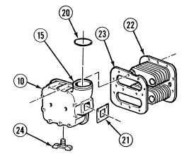
Remove and discard seal (20) from water
outlet (15).
(13)
Remove and discard gasket (21) from oil
cooler (10).
(14)
Remove oil cooler core (22) and gasket (23)
from oil cooler (10). Discard gasket.
(15)
Remove drain cock (24) from oil cooler (10).
|