|
| |
TM 9-2320-364-34-2
4-30
4-6. BLOWER DRIVE ASSEMBLY REPLACEMENT (CONT).
(3)
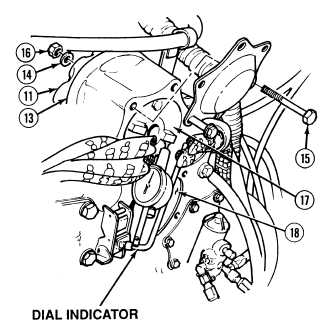
Install washer (14), screw (15) and nut (16)
in top of blower drive assembly (11) and
draw blower drive assembly tight to flywheel
housing (13).
NOTE
Backlash must be 0.002 in. to
0.010 in. (0.051 to 0.254 mm).
(4)
Position dial indicator on blower drive
gear (17) and check backlash between
blower drive gear and right back camshaft
gear (18).
(5)
If backlash is below minimum specification,
replace blower drive assembly.
(6)
Remove nut (16), screw (17) and
washer (14) from blower drive assembly
(11).
(7)
Remove dial indicator from blower drive
gear (17).
(8)
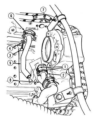
Install hose (2) and two clamps (1) on
breather tube (8).
(9)
Install gasket (6) and breather tube (5) on
right cylinder head (7) with two
lockwashers (4) and screws (3). Tighten
screws to 60 lb-in (7 N.m).
(10)
Tighten two clamps (1) on hose (2).
c.
Follow-On Maintenance:
Install blower, (Para 4-4).
Remove wheel chocks, (TM 9-2320-364-10).
END OF TASK
|


