|
| |
TM 9-2320-364-34-2
3-6
3-2. ENGINE ADJUSTMENTS (CONT).
b.
Engine Brake Retarder Adjustment.
To prevent engine damage ensure exhaust valves are closed and injector follower is fully
depressed.
Crankshaft must be turned clockwise only. If crankshaft is turned counterclockwise,
crankshaft screw will be loosened resulting in damage to equipment.
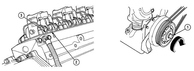
(1)
With the aid of an assistant, rotate crankshaft by turning pulley (1) clockwise until engine is on injection
stroke. Injector push rods (2) will be fully up, and exhaust push rods (3) will be down.
NOTE
Use 0.059 in. (1.5 mm) feeler
gage for hot or cold setting.
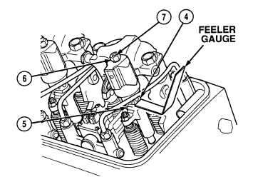
(2)
Insert feeler gage between slave piston
foot (4) and exhaust valve bridge (5).
(3)
Loosen nut (6) and turn adjusting screw (7)
until slight drag is felt on feeler gage.
(4)
Check both feet of slave piston (4).
(5)
Tighten nut (6) to 180 to 216 lb-in
(20 to 24 N.m) and recheck clearance.
(6)
Repeat Steps (1) through (5) for other seven
engine brake retarders.
|