|
| |
TM 9-2320-364-34-2
7-8
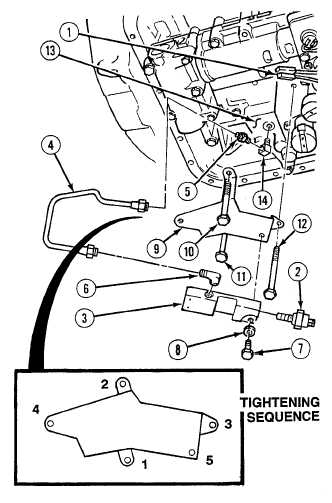
7-5. TRANSMISSION LOW OIL SENSOR ASSEMBLY REPLACEMENT (CONT).
b.
Installation.
NOTE
Install fittings as noted prior to
removal.
(1)
Install elbow (6) in low oil sensor body (3).
(2)
Install elbow (14) and adapter (5) on valve
body (3).
(3)
Position sensor bracket (9) with screws (12),
(11) and (10) in valve body (13).
(4)
Position low oil sensor body (3), with two
washers (8) and screws (7) on sensor bracket
assembly (9).
(5)
Install oil pressure switch (2) in low oil
sensor body (3).
NOTE
Step (6) includes all screws
on control valve assembly,
solenoid assembly and valve
assemblies.
If screw binds during
installation, loosen all
screws, check alignment of
control valve and
components and repeat
tightening procedure until
all screws can be tightened
without binding.
(6)
Using sequence shown, tighten screws finger tight starting with screw closest to center of control valve
body. Using same sequence, tighten all screws to 96 to 144 lb-in (11 to 16 N.m).
(7)
Install low oil sensor tube assembly (4) on elbow (6) and adapter (5).
(8)
Install two connectors (1) on low oil sensor switch (2).
c.
Follow-On Maintenance:
Install internal oil filter, (Para 7-4).
Remove wheel chocks, (TM 9-2320-364-10).
END OF TASK
|