|
| |
TM 9-2320-364-34-2
7-7
Materials/Parts
Tags, Identification (Item 72, Appendix B)
This task covers:
a. Removal
b. Installation
c. Follow-On Maintenance
INITIAL SETUP
Equipment Condition
Engine OFF, (TM 9-2320-364-10)
Wheels chocked, (TM 9-2320-364-10)
Internal oil filter removed, (Para 7-4)
Tools and Special Tools
Tool Kit, General Mechanic’s
(Item 240, Appendix F)
Wrench, Combination 1-1/16 in.
(Item 254, Appendix F)
Wrench Set, Socket 3/8 in. Drive
(Item 273, Appendix F)
Wrench, Torque (0-60 N.m)
(Item 276, Appendix F)
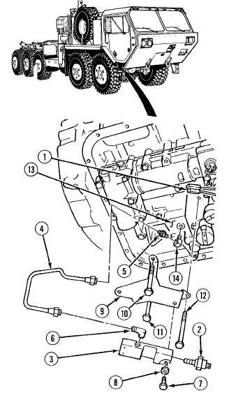
7-5. TRANSMISSION LOW OIL SENSOR ASSEMBLY REPLACEMENT.
a.
Removal.
NOTE
Tag and mark all wires prior to
removal.
(1)
Remove two connectors (1) from low oil
sensor switch (2).
(2)
Remove low oil sensor switch (2) from low
oil sensor body (3).
(3)
Remove low oil sensor tube assembly (4)
from adapter (5) and elbow (6).
(4)
Remove two screws (7), washers (8) and low
oil sensor body (3) from bracket
assembly (9).
(5)
Remove screws (10), (11) and (12) and
sensor bracket (9) from valve body (13).
NOTE
Note position of fittings prior to
removal.
(6)
Remove adapter (5) and elbow (14) from
valve body (13).
(7)
Remove elbow (6) from low oil sensor
body (3).
|