|
| |
TM 9-2320-364-34-2
9-24
9-4. AXLE NO. 2 ASSEMBLY REPLACEMENT (CONT).
NOTE
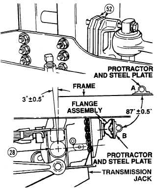
Equalizer beams and frame must be level to perform axle camber adjustment properly.
Axle camber angle measurements must be taken with relationship to frame. If frame is not
level, the angle the frame is inclined must be added or subtracted from flange assembly
measurement.
Axle flange assembly measurement of 87 degrees 0.5 degrees equals axle camber of
three degrees 0.5 degrees (90 degrees - 87 degrees = 3 degrees).
(13)
Measure the angle (in degrees) that flange
assembly (9) is cambered.
(a)
Position protractor and steel plate on
frame at point A. Adjust protractor to
zero degrees.
(b)
Position protractor and steel plate on
machined surface of the flange
assembly (9) at point B and record
measurement. Measurement should
read 87 degrees 0.5 degrees.
(14)
If axle camber is not three degrees 0.5
degrees, add or subtract spacers (52) until
axle camber is correct.
(15)
Remove transmission jack from Axle
No. 2 (28).
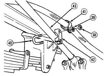
(16)
Install U-bolt half (42), U-bolt (40) and
clamp (41) on torque rod (43) with two
lockwashers (39) and nuts (38).
|