|
| |
TM 9-2320-364-34-2
9-37
(3)
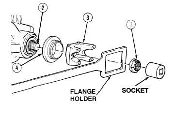
Install dust cover (4) on flange assembly (3).
NOTE
Flange assembly should be
positioned so large openings of
flange assembly align with slots
of pinion shaft. This will ease
staking of nut.
(4)
Install flange assembly (3) on pinion
shaft (2).
Adhesives, solvents, and sealing
compounds can burn easily, can
give off harmful vapors, and are
harmful to skin and clothing. To
avoid injury or death, keep away
from open fire and use in a well-
ventilated area. If adhesive,
solvent, or sealing compound
gets on skin or clothing, wash
immediately with soap and
water.
(5)
Coat threads of pinion shaft (2) and face of
flange assembly (3) where adjusting nut (1)
seats with adhesive.
(6)
With the aid of an assistant and using flange
holder and socket, install adjusting nut (1)
on pinion shaft (2). Tighten adjusting nut to
486 to 572 lb-ft (659-776 N.m).
(7)
Ensure adhesive has squeezed out around
entire outside diameter of adjusting nut (1).
If adhesive is not visible around entire
outside diameter of adjusting nut (1),
remove and discard adjusting nut (1) and
repeat Steps (5) and (6).
(8)
Stake adjusting nut (1) in two slots of pinion
shaft (2) directly 180 degrees apart.
c.
Follow-On Maintenance:
Connect driveshaft, (TM 9-2320-364-20).
Check axle oil level, (TM 9-2320-364-20).
Remove wheel chocks, (TM 9-2320-346-10).
END OF TASK
|