|
| |
TM 9-2320-364-34-2
9-50
9-9. AXLE NO. 1, 2 AND 5 PIVOT AND SPINDLE ASSEMBLY AND OUTER AXLE
SHAFT SEAL AND BEARING REPLACEMENT (CONT).
(20)
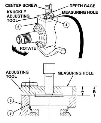
Install knuckle adjusting tool on pivot and
spindle assembly (5) with two screws (4).
Tighten screws to 200 lb-ft (271 N.m).
(21)
Install center screw of adjusting tool.
Tighten center screw to 200 lb-ft (271 N.m).
(22)
Loosen center screw slightly until pivot and
spindle assembly (5) rotates freely.
(23)
Center pivot and spindle assembly (5).
(24)
Tighten center screw in adjusting tool to 50
lb-ft (68 N.m).
NOTE
Measure distance through
measuring hole.
(25)
Using depth gage, measure distance from
top of adjusting tool to top of pivot and
spindle assembly (5) and record as
dimension A.
(26)
Using depth gage, measure distance from top of
dimension B.
(27)
Subtract dimension A from dimension B (B - A). The answer is the gap between pivot and spindle
assembly (5) and top of trunnion (8).
(28)
Refer to Table 9-1 to determine shim (7) thickness.
(29)
Remove two screws (4) and adjusting tool.
Table 9-1. Determining Shim Thickness
Gap between pivot and spindle
assembly and trunnion
Shim thickness
0.018 to 0.022 in. (0.46 - 0.56 mm)
0.016 in. (0.4 mm)
0.022 to 0.026 in. (0.56 - 0.66 mm)
0.020 in. (0.5 mm)
0.026 to 0.030 in. (0.66-0.76 mm)
0.024 in. (0.6 mm)
0.030 to 0.033 in. (0.76-0.84 mm)
0.028 in. (0.7 mm)
0.033 to 0.037 in. (0.84-0.94 mm)
0.031 in. (0.8 mm)
0.037 to 0.041 in. (0.94-1.04 mm)
0.035 in. (0.9 mm)
0.041 to 0.045 in. (1.04-1.14 mm)
0.039 in. (1.0 mm)
|