|
| |
TM 9-2320-364-34-2
9-71
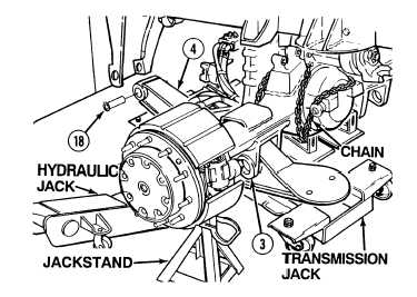
Trailing beam assembly weighs
150 lbs (68 kg). Attach a
hydraulic jack to axle end of air
suspension beam assembly prior
to installation to prevent
possible injury to personnel.
NOTE
Both trailing beam assemblies
are installed the same way. Left
side of Axle No. 3 is shown.
(6)
Position trailing beam assembly (4) on
hydraulic jack and install plastic bushing
(18) in trailing beam assembly.
(7)
Using hydraulic jack, position trailing beam
assembly (4) below Axle No. 3 (3).
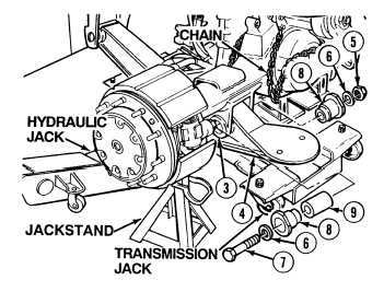
(8)
Coat threads of screw (7) with lubricating
oil.
Keep fingers out of trailing beam
assembly holes. Failure to
comply could result in serious
injury to personnel.
(9)
Position spacer (9) in Axle No. 3 (3) and
trailing beam assembly (4).
(10)
Apply a thin coat of lubricating oil on
adapters (8).
(11)
Position adapter (8), washer (6), screw (7),
adapter (8), washer (6) and nut (5) in axle
(3) and trailing beam assembly (4).
|