Order this information in Print

Order this information on CD-ROM

Download in PDF Format


Click here to make tpub.com your Home Page

Page Title: Position trailing beam assembly
Back | Up | Next

Click here for a printable version

Google


Web
www.tpub.com

Home


Information Categories
.... Administration
Advancement
Aerographer
Automotive
Aviation
Combat
Construction
Diving
Draftsman
Engineering
Electronics
Food and Cooking
Math
Medical
Music
Nuclear Fundamentals
Photography
Religion
USMC
   
Products
  Educational CD-ROM's
Printed Manuals
Downloadable Books


TM 9-2320-364-34-2 9-72      9-11.  AXLE NO. 3 ASSEMBLY REPLACEMENT (CONT). NOTE Axle may need slight adjustment for proper alignment in frame hanger. (12) 
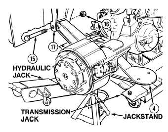
Using transmission jack, raise trailing beam assembly (4) and position in trailing beam assembly mount (17). (13) Position trailing beam assembly (4) in trailing beam assembly mount (17) with screw (15) and nut (16). Ensure axle is fully supported by jackstands prior to removing hydraulic jack from trailing beam assembly.  Failure to comply may result in injury to personnel. (14) Remove hydraulic jack from below trailing beam assembly (4). (15) Repeat Steps (5) through (14) for remaining trailing beam assembly (4).

Privacy Statement - Press Release - Copyright Information. - Contact Us - Support Integrated Publishing

Integrated Publishing, Inc. - A (SDVOSB) Service Disabled Veteran Owned Small Business