|
| |
TM 9-2320-364-34-2
9-73
Keep hands and feet clear of Axle No. 3 until Axle No. 3 is secured by longitudinal torque rod.
Failure to comply may result in injury to personnel.
NOTE
It may be necessary to raise front of differential with floor jack to aid in installation of
longitudinal torque rod.
(16)
With the aid of an assistant, position axle
end of torque rod (56) on Axle No. 3 (3)
with two washers (58), screws (59), washers
(58) and locknuts (57).
NOTE
Install same number and size
spacers in their original location
that they were removed from.
(17)
With the aid of an assistant, install
plate (62), spacers (64), bracket (63) and end
of torque rod (56) with two screws (61) and
locknuts (60).
(18)
With the aid of an assistant, tighten
locknuts (57) on screws (59).
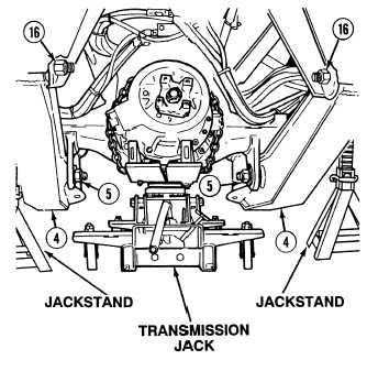
(19)
With the aid of an assistant, tighten two
locknuts (5) on trailing beam assemblies (4)
210 to 240 lb-ft (285 to 325 N.m).
(20)
With the aid of an assistant, tighten two
locknuts (16) on trailing beam
assemblies (4) to 800 lb-ft (1085 N.m).
|