|
| |
TM 9-2320-364-34-2
9-100
9-13. AXLE NO. 5 ASSEMBLY REPLACEMENT
(8)
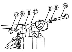
Install axle end of torque rod (51) and air
manifold bracket (50) on Axle No. 5 (37)
with two screws (49), four washers (48) and
two locknuts (47).
NOTE
Equalizer beams and frame must be level to perform axle camber adjustment properly.
Axle camber angle measurements must be taken with relationship to frame. If frame is not
level, the angle the frame is inclined must be added or subtracted from flange assembly
measurement.
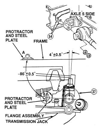
Axle flange measurement of 86 0.5 degrees equals axle camber of four degrees 0.5 (90
degrees – 86 degrees = 4 degrees).
(9)
Position protractor and steel plate on frame
at point A. Adjust protractor to zero.
(10)
Position protractor and steel plate on
machined surface of the flange assembly
and record measurement. This is point B.
Measurement should read 86 degrees 0.5
degrees.
(11)
Subtract measurement recorded at point B
from 90 degrees. This will be axle camber.
Axle No. 4 and Axle No. 5 share
mounting hardware for
longitudinal torque rods. Both
axles must be supported during
removal of screws and locknuts
or axles may fall. Failure to
comply may result in injury or
death to personnel.
(12)
If Axle No. 5 camber is not four degrees
0.5 degrees, support Axle No. 4 and add or
subtract spacers (54) until correct axle
camber is achieved.
(13)
Remove transmission jack from
Axle No. 5 (37).
|


