|
| |
TM 9-2320-364-34-3
16-64
Materials/Parts
Compound, Antiseize (Item 14, Appendix B)
This task covers:
a. Removal
b. Installation
c. Follow-On Maintenance
INITIAL SETUP
Personnel Required
Two
Equipment Condition
Engine OFF, (TM 9-2320-364-10)
Wheels chocked, (TM 9-2320-364-10)
Tools and Special Tools
Tool Kit, General Mechanic’s
(Item 240, Appendix F)
Cap and Plug Set (Item 26, Appendix F)
Pan, Drain 6 gal (Item 145, Appendix F)
Wrench, Torque (0 to 175 lb-ft [0-237 N.m])
(Item 277, Appendix F)
Lifting Device, Minimum Capacity 150 lbs
(68 kg)
Wooden Block (Appendix C)
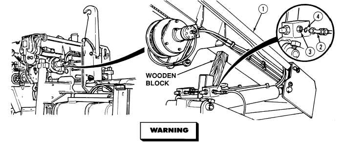
16-6. LIFT CYLINDER REPLACEMENT.
Materials/Parts - Continued
Oil, Hydraulic (Item 34, Appendix B)
Sealing Compound (Item 56, Appendix B)
Tags, Identification (Item 72, Appendix B)
Packing, Preformed (Item 384, Appendix E)
Packing, Preformed (2) (Item 389, Appendix E)
The crane hydraulic system operates at oil pressures up to 3,100 psi (21,375 kPa). Never
disconnect any hydraulic line or fitting without first dropping the pressure to zero. Failure
to comply may result in serious injury or death to personnel.
NOTE
Left and right side lift cylinders are removed the same way. Left side shown.
Tag and mark hydraulic hoses prior to removal.
Cap and plug hydraulic hoses and cylinder after removal.
(1)
Raise boom (1) and support with wooden block.
(2)
Disconnect two hoses (2) from fittings (3) and remove two preformed packings (4). Discard preformed
packings.
|