|
| |
TM 9-2320-364-34-3
16-69
Materials/Parts
Oil, Hydraulic (Item 34, Appendix B)
This task covers:
a. Removal
b. Installation
c. Follow-On Maintenance
INITIAL SETUP
Equipment Condition
Engine OFF, (TM 9-2320-364-10)
Wheels chocked, (TM 9-2320-364-10)
Tools and Special Tools
Tool Kit, General Mechanic’s
(Item 240, Appendix F)
Cap and Plug Set (Item 26, Appendix F)
Pan, Drain, 6 gal (Item 145, Appendix F)
Wrench, Combination 1-1/8 in.
(Item 255, Appendix F)
16-7. LIFT CYLINDER HOLDING VALVE REPLACEMENT.
Materials/Parts - Continued
Tags, Identification (Item 72, Appendix B)
Packing, Preformed (Item 364, Appendix E)
The crane hydraulic system operates at oil pressures up to 3,100 psi (21,375 kPa). Never
disconnect any hydraulic line or fitting without first dropping the pressure to zero. Failure
to comply may result in serious injury or death to personnel.
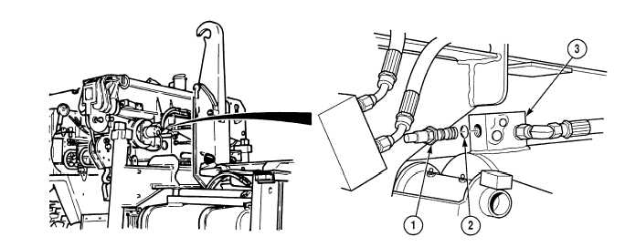
NOTE
Holding valves are removed the same way from left and right side lift cylinders. Left side
shown.
Plug lift cylinder after disconnecting.
a.
Removal. Remove holding valve (1) and preformed packing (2) from lift cylinder (3). Discard preformed
packing.
|