|
| |
TM 9-2320-364-34-3
16-124
16-18. SWING DRIVE GEAR REDUCER REPLACEMENT (CONT).
b.
Installation.
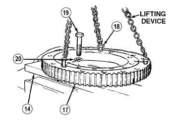
Bearing gear weighs 135 lbs. (61 kg). Attach suitable lifting device prior to installation to
prevent possible injury to personnel.
NOTE
Perform Steps (1) through (20) if installing a new gear reducer.
If installing original gear reducer, go to Step (21).
Screws used in Step (1) were removed with turntable.
(1)
Attach lifting device to bearing gear (17)
with three screws (18).
NOTE
Letter G stamped on bearing
faces down and centered on
subframe.
(2)
Position bearing gear (17) on subframe (14).
(3)
Install 16 screws (19) and washers (20) in
bearing gear (17). Tighten screws to 333
lb-ft (452 N.m).
(4)
Remove three screws (18) and lifting device
from bearing gear (17).
(5)
Install spacer ring (15) on gear reducer (3)
with nine screws (12) and washers (13).
Tighten screws to 99 lb-ft (134 N.m).
|