|
| |
TM 9-2320-364-34-3
17-31
NOTE
Note location and position
of elbows prior to removal.
If removing front control
subassembly, perform
Steps (7) and (8).
If removing rear control
subassembly, perform
Steps (9) and (10).
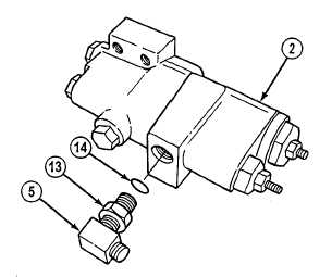
(7)
Position front control subassembly (2) in
soft jawed vise.
(8)
Loosen nut (13) and remove elbow (5) and
preformed packing (14) from front control
subassembly (2). Discard preformed
packing.
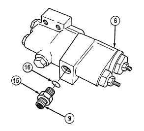
(9)
Position rear control subassembly (6) in soft
jawed vise.
(10)
Loosen nut (15) and remove adapter (9)
and preformed packing (16) from rear
control subassembly (6). Discard
preformed packing.
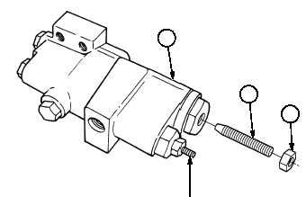
b.
Disassembly.
Outside pump control setscrew is
factory adjusted and should not
be removed or adjusted. Removal
or adjustment of outside pump
control setscrew could result in
damage to truck hydraulic system
and components. Remove inside
pump control setscrew only.
NOTE
Disassembly of front control
subassembly and rear control
subassembly are identical. Front
control subassembly is shown for
disassembly.
(1)
Position front control subassembly (1) in
soft jawed vise.
(2)
Remove jam nut (2) and adjusting screw (3)
from front control subassembly (1).
OUTSIDE PUMP
CONTROL SETSCREW
(DO NOT ADJUST)
1
3
2
|