|
| |
TM 9-2320-364-34-3
18-125
a.
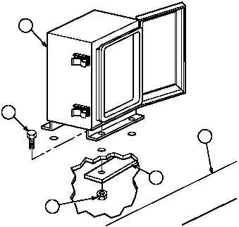
Installation.
NOTE
This task pertains to vehicles that have been field retrofit with 200 AMP alternator.
(1)
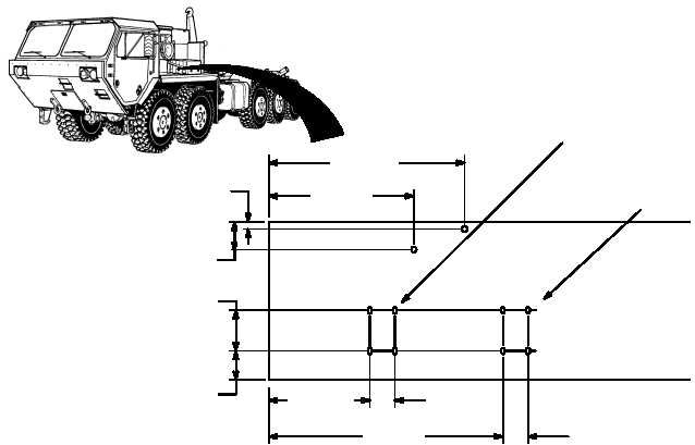
Mark switch box and clamp hardware mounting locations on left fender.
(2)
Drill six .344 in. (11/32 in.) (8.74 mm) holes in fender (1) at locations marked in Step (1).
(3)
Install four screws (2) through battery
disconnect switch box (3) and fender (1).
(4)
Position two mounting brackets (4) on four
screws (2) and secure with four nuts (5).
3
4
2
5
1
LOCATION
WITH
ARTIC KIT
LOCATION
WITHOUT
ARTIC KIT
30.25 IN.
(76.84 CM)
22.25 IN.
(56.52 CM)
0.75 IN.
(19.05 MM)
6.25 IN.
(15.88 CM)
5.85 IN.
(14.86 CM)
4.5 IN.
(11.43 CM)
15.25 IN.
(38.74 CM)
35.5 IN.
(90.17 CM)
3.85 IN.
(9.78 CM)
3.85 IN.
(9.78 CM)
|