|
| |
TM 9-2320-364-34-3
18-143
(1)
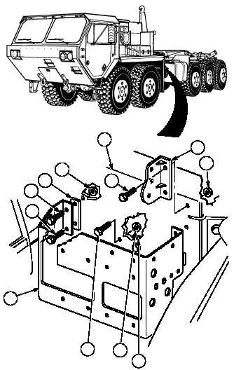
Remove two screws (1), locknuts (2) and
gear reducer mount (3) from frame (4).
Discard screws, locknuts and gear reducer
mount.
(2)
Remove top two screws (5) and locknuts (6)
from intermediate crossmember (7). Discard
screws and locknuts.
NOTE
Retain bottom front screw from
air dryer bracket for assembly.
(3)
With the aid of an assistant, support air
dryer bracket (8) and remove front two
screws (9) and (10), spacer (11) and two
locknuts (12). Discard screw (9) and
locknuts.
(4)
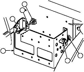
Rotate spacer (11) 90 degrees and position
screw (10), spacer (11) and locknut (13) on
air dryer bracket (8). Do not tighten.
(5)
Loosen bottom rear screw (14) and locknut
(13) on air dryer bracket (8). Do not
remove.
1
2
3
4
7
8
9
10
11
12
5
6
AIR DRYERS AND
FUEL WATER
SEPARATOR
SHOWN REMOVED
FOR CLARITY
13
10
8
11
14
13
AIR DRYERS AND
FUEL WATER
SEPARATOR
SHOWN REMOVED
FOR CLARITY
|


