|
| |
TM 9-2320-364-34-3
13-43
f.
Rear Tandem Crossmember Installation.
NOTE
Install cable ties as required.
(1)
Position rear tandem crossmember (15) in
right and left rear tandem gussets (23).
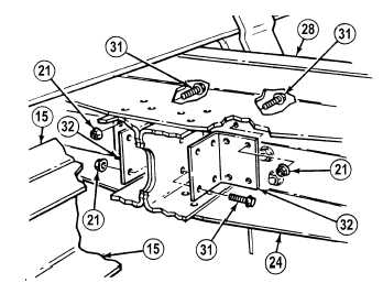
(2)
With the aid of an assistant, install two left
side angles (32) on rear tandem
crossmember (15), left side gusset (23) and
frame (28) with eight screws (34), two
screws (31) with ten locknuts (21).
NOTE
If rear cable tensioner was
removed, Step (3) will only
install ten screws and locknuts.
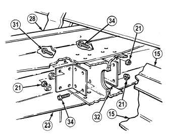
(3)
With the aid of an assistant, install two right
side angles (32), on rear tandem
crossmember (15), right side gussets (24)
and frame (28) with twelve screws (31)
twelve locknuts (21).
(4)
With the aid of an assistant, install twelve
screws (22) in rear upper gussets (30) and
rear tandem crossmembers (15) with twelve
locknuts (21).
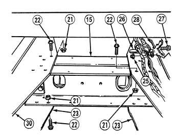
(5)
Install twelve screws (22) in rear lower
gussets (24) and rear tandem crossmember
(15) with twelve locknuts (21).
(6)
Install bracket (26) on frame (28) with screw
(27) and locknut (25).
|