|
| |
TM 9-2320-364-34-4
20-161
(7)
Inspect drive gear teeth for scoring, pitting, and burning (blue or dark spots). Replace if teeth are
damaged.
(8)
Inspect accessory drive hub for cracks, breaks, stripped threads or worn-out splines in bore. Replace if
damaged.
(9)
Inspect both flex spring plates for cracks, distortion, or other damage. Replace if damaged.
(10)
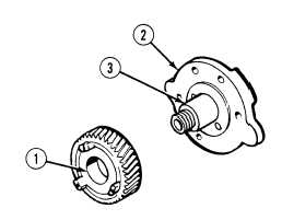
Using a telescoping gage and micrometer,
check that inside diameter of drive gear
bushings (1) is between 1.6260 and 1.6265 in.
(41.300 and 41.313 mm). Record diameter.
(11)
Using a micrometer, check diameter of blower
drive support (2) at base of shaft (3).
Diameter must be between 1.6240 and 1.6265
in. (41.250 and 41.313 mm). Record
diameter.
(12)
Subtract diameter recorded in Step (10)
from diameter recorded in Step (11).
Clearance between blower drive support
(2) and support bushing (1) is between
0.0010 and 0.0025 in. (0.025 and 0.064
mm) when parts are new. Limit is 0.0050
in. (0.127 mm) for used parts.
c.
Assembly.
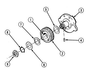
(1)
Apply lubricating oil to support bushings (1)
in drive gear (2).
(2)
Place blower drive assembly (3) in vise with
soft jaws.
(3)
Install pin (4) in blower drive assembly (3).
(4)
Apply light coat of lubricating oil to blower
drive assembly (3), thrust washer bearing
(5) and thrust washer bearing (6).
(5)
Install thrust washer bearing (5) on blower
drive assembly (3).
(6)
Install drive gear (2) with flat side towards
blower drive assembly (3).
(7)
Install thrust washer bearing (7) and thrust
washer bearing (6) with tang of thrust
washer bearing fitting in thrust washer
bearing notch on blower drive assembly (3).
(8)
Install lockwasher (8) and nut (9), with
lockwasher tang fitting in thrust washer
bearing (7) notch on blower drive
assembly (3). Tighten nut 50 to 60 lb-ft (68
to 81 N.m).
|


