|
| |
TM 9-2320-364-34-4
20-299
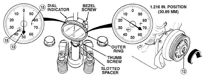
NOTE
Dial indicator must be zeroed before piston downward travel can be measured. Perform
Steps (10) through (12) to measure downward travel.
(10)
Loosen thumbscrew and remove slotted spacer.
(11)
Lower dial indicator until two small dial hands (15) are at zero and large dial hand (13) is near zero.
Tighten thumbscrew.
(12)
Loosen bezel screw and rotate outer ring of dial until zero lines up with large dial hand (13). Tighten
bezel screw.
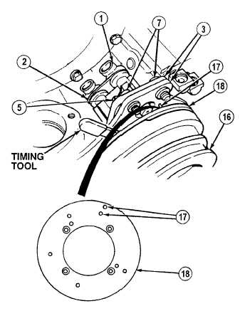
NOTE
Perform Steps (13) through (19)
for DDEC II engines.
(13)
Turn crankshaft (12) slowly clockwise, until
dial reads exactly 1.216 in. (30.886 mm).
(14)
Tap end of camshaft pulley (16) to take up
end play.
(15)
Insert grooved end of timing tool between
TRS (2) and double teeth (17) on pulse
wheel (18).
(16)
Move bracket (3) to align end of TRS (2)
with groove in timing tool.
(17)
Hold bracket (3) and tighten two screws (7).
(18)
Check that synchronous reference sensor
(1) is in place against half moon on rear of
timing tool and double teeth on pulse
wheel (18) in groove on front of timing
tool.
(19)
Tighten screw (5) and remove timing tool.
|