|
| |
TM 9-2320-364-34-4
20-300
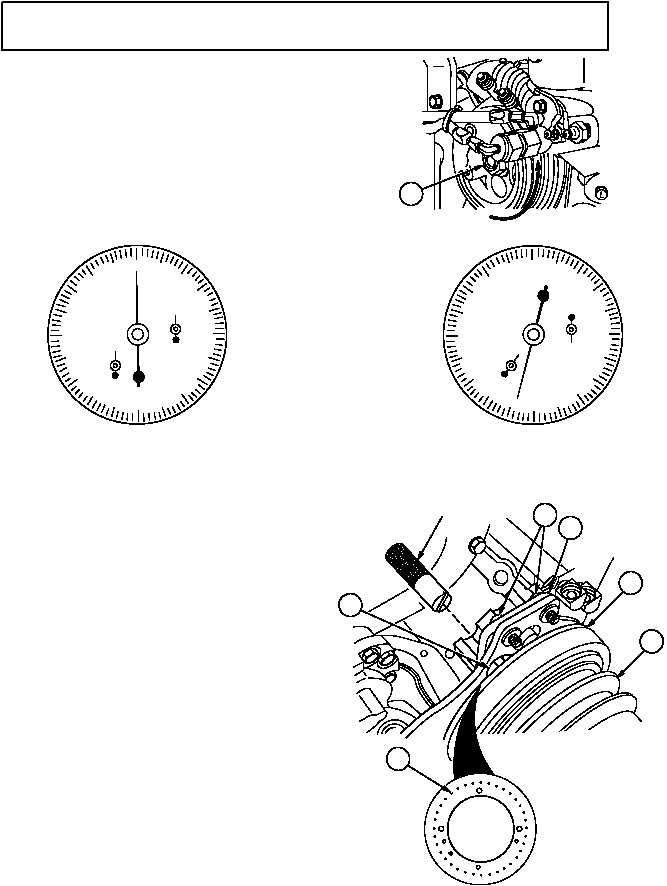
20-91. TIMING AND SYNCHRONOUS REFERENCE SENSOR (TRS/SRS)
INSTALLATION (CONT).
NOTE
Preform Steps (20) through (29)
for DDEC III engines.
(20)
Zero dial indicator and turn camshaft (14)
slowly counterclockwise, until dial
indicates exactly 2.146 in. (54.51 mm).
(See below).
(21)
Tap end of camshaft pulley (19) with
soft-faced hammer to take up end play.
(22)
Insert alignment tool in TRS hole (20) of
bracket (21).
NOTE
There is a notch on the edge of
the pulse wheel next to the
correct TRS timing pin.
(23)
Move bracket (21) until notch in tool
engages with TRS timing pin (22) on pulse
wheel (23).
(24)
Tighten two sockethead screws (24) and
remove alignment tool.
(25)
Tap end of camshaft pulley (19) again to
take up end play.
0
50
20
10
30
40
60
70
80
90
ZERO POSITION
1
2
0
3
4
5
6
7
8
9
0
2
1
2.146 IN. POSITION
0
50
20
10
30
40
60
70
80
90
1
2
0
3
4
5
6
7
8
9
0
2
1
ALIGNMENT
TOOL
14
24
21
19
23
20
22
|